Carbon fiber can give a cement-based mixture a useful combination of crack bridging, low fiber weight, and electrical conductivity. It also creates a demanding production problem: fine, chopped filaments tend to cling together. A strong fiber on a data sheet will do little for a concrete element if most of the filaments remain in bundles.
At Shandong Jianbang Chemical Fiber Co., Ltd., we look at carbon fiber concrete as a complete material system. The fiber grade, aggregate, paste, dispersing method, mixer, placement process, and curing plan must be chosen together. This guide shows how to move from raw-material selection to a controlled trial, then to a repeatable production process. It also explains which claims require a test before they belong in a project specification.
What is carbon fiber concrete?
Carbon fiber concrete contains short carbon filaments distributed through a cementitious matrix. The fibers may cross a developing crack and transfer some load while the crack opens. Depending on dispersion, contact between fibers, and moisture conditions, the material may also show an electrical response. These are two different design goals. A mixture that works for flexural performance is not automatically an accurate strain sensor or a conductive overlay.
Most chopped fibers used in research and specialty cement mixes are made from a polyacrylonitrile, or PAN, precursor. Pitch-based and rayon-based carbon fibers are other material families. The carbonized PAN fiber discussed here is not the same product as an ordinary PAN synthetic fiber. A continuous carbon-fiber fabric or a carbon-fiber-reinforced polymer sheet is also a different reinforcement system from chopped filaments mixed into concrete. State the fiber form in every inquiry and test report.
The main selection question is practical: can the chosen filament be separated, wetted, retained in the mixer, and distributed through the element without unacceptable loss of workability? Only then can its tensile strength and stiffness contribute to the intended performance.
Select materials for the intended concrete system
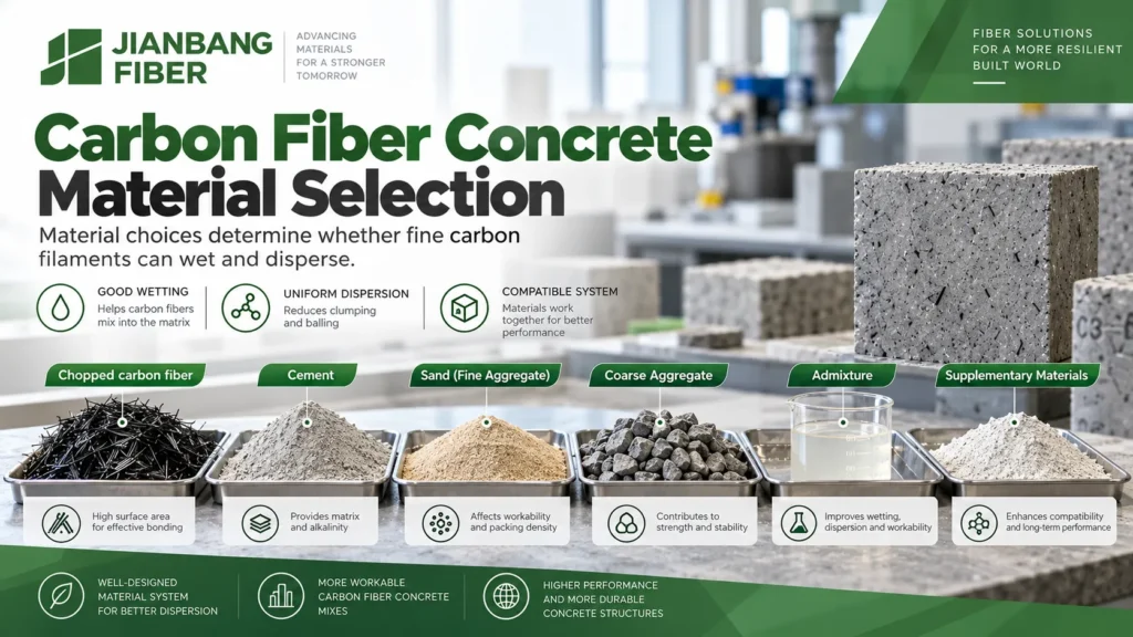
Choose the carbon fiber by grade and surface condition
Ask for the specific fiber’s precursor, length distribution, nominal diameter, tensile properties, sizing or surface treatment, moisture, and packaging. Some initial laboratory screens use chopped lengths around 5–25 mm and fine filaments near 7–8 micrometers in diameter. These figures describe examples to investigate, not a universal Ecocretefiber™ catalog specification or a required range for every concrete. A very long or fine filament may raise the tendency to clump. A shorter fiber may distribute more easily but bridge a crack differently.
Surface treatment can improve wetting or the bond between the fiber and matrix, but an organic sizing developed for resin composites may not behave the same way in alkaline cement paste. Test the actual delivered grade. Ask whether the product arrives as dry chopped fibers, a pre-dispersed form, or another package, and whether the selected process can separate individual filaments. High nominal fiber tensile strength alone cannot predict the concrete’s residual flexural strength.
Build the binder and aggregate around workability
Start with cement that meets the project’s structural and exposure requirements. Portland cement or a blended cement may be appropriate. A cement strength class such as 42.5 can be one project input, but it is not a universal minimum imposed by the presence of carbon fibers. Specify cement and supplementary cementitious materials under the governing local standards.
Use clean, well-graded sand and coarse aggregate. Maximum aggregate size must fit the element, cover, placing method, and fiber length. A laboratory guide may screen coarse aggregate at 20 mm or smaller, while a thin repair layer may need much smaller particles or even mortar. The right grading helps the mix flow and can reduce localized fiber concentration. It does not make a poorly dispersed fiber suddenly uniform.
Fly ash, slag, and silica fume can change paste volume, cohesion, strength development, and durability. Silica fume has also been investigated as part of carbon-fiber dispersion strategies. The binder replacement level should follow the target exposure and trial results. Do not copy a single 20–40% substitution from one formulation into every mix. Water reducer, air entrainer, defoamer, or a dispersant may also be needed, but each can interact with the fiber surface and the other admixtures. Verify compatibility and air content in the full mixture.
Design a trial mix before choosing fiber dosage
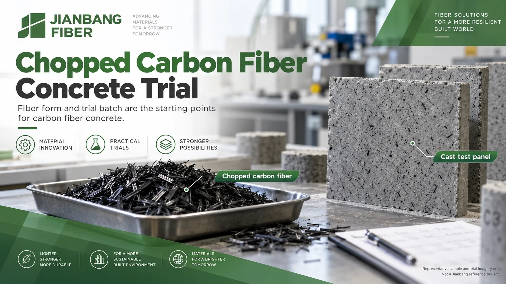
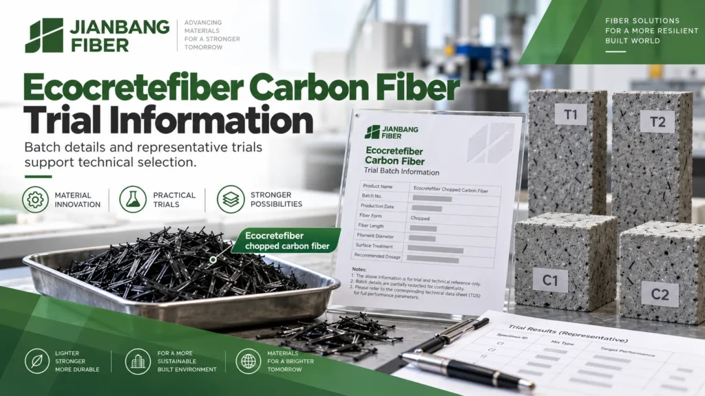
Begin with a fiber-free control mixture that meets the required strength, fresh workability, durability, and placement criteria. Then vary one carbon-fiber parameter at a time where practical. Document the dose clearly as percent by volume of concrete, mass per cubic meter, or mass relative to cement. Those three units are not interchangeable. Report fiber density and the conversion used when a comparison calls for it.
Research and development trials may explore a wide window such as 0.1–1.5% fiber by concrete volume. That is an exploratory range, not a production recommendation. A 0.5% trial is one candidate, not a proven optimum. The viable level depends on fiber length, available paste, aggregate, dispersion method, cost, and the desired mechanical or electrical result. More fiber may form clusters, trap air, lower flow, or make casting less reliable.
| 시험 변수 | Record during mixing | Decide from the results |
| Fiber grade and length | Exact batch, form, surface treatment, and condition | Does the grade disperse and meet the project target? |
| Fiber amount | Volume fraction and actual mass per batch | Does the added amount improve performance without excessive workability loss? |
| Paste and aggregate | Binder, sand ratio, maximum aggregate size, and water | Can the mix wet fibers and fill the element? |
| Dispersion aid | Admixture identity, dose, sequence, and air content | Does it separate fibers without harming the matrix? |
| Mixer and sequence | Mixer type, batch size, addition rate, and mixing energy | Can the method be repeated at production scale? |
At each trial level, test fresh concrete and specimens made by the intended placement method. A rise in a laboratory beam result does not justify production if the field mixer leaves bundles in the concrete. Likewise, a good slump does not prove uniform filament distribution. Keep a photograph and a batch record for every variation.
Mix carbon fibers without forming bundles
Compare dry distribution and wet pre-dispersion
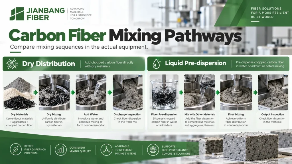
One possible sequence is to blend a measured amount of chopped fiber into a portion of dry fine material, then introduce it into the moving aggregate and binder before adding the remaining water and admixture. Another is to pre-disperse the fiber in part of the mixing liquid with a compatible dispersing aid, then add that suspension to the mixer. A third is to make a workable mortar phase first and add fibers gradually before the remaining aggregate. Each route changes fiber separation, air, wetting, and mixing time. Trial results should select the route.
Published experiments on chopped carbon fiber cement composites found that pre-dispersion and the dispersant type affected the final fiber distribution. In one specific study, ultrasonic pre-dispersion improved separation and hydroxyethyl cellulose performed differently from methyl cellulose and sodium carboxymethyl cellulose. That finding supports a controlled comparison; it is not a universal instruction to add HEC or use ultrasound in a ready-mix plant. The required concentration, water balance, viscosity, and scale-up behavior must be tested for the actual formulation. Read the experimental study on dispersants and molding.
Scale up the approved addition sequence
A forced-action mixer may offer useful shearing and repeatability, especially for trials, but its name does not guarantee good dispersion. Add fibers at a steady rate to avoid a concentrated clump. Confirm the wetting of fibers and inspect discharge samples from more than one part of the batch. Establish a minimum mixing energy or time through trials, then check whether extra mixing changes fiber length, entrained air, slump, or temperature.
Some hand-mixing protocols begin with a short dry phase followed by a wet phase, and some use staged fiber addition into mortar. Values such as one or two minutes dry and two or three minutes wet should be treated as laboratory starting conditions. Plant mixer capacity, fill level, blade design, fiber form, and batch size can make those timings unsuitable. Record the actual production settings that reproduce the trial result.
If visible bundles remain, stop and diagnose the cause. Check whether the package was added too fast, whether fiber was already clumped, whether the paste can wet the filaments, and whether the dispersant is compatible. Do not automatically add water. Uncontrolled water changes the mixture that was qualified for strength and durability.
Place and cure the concrete as a tested system
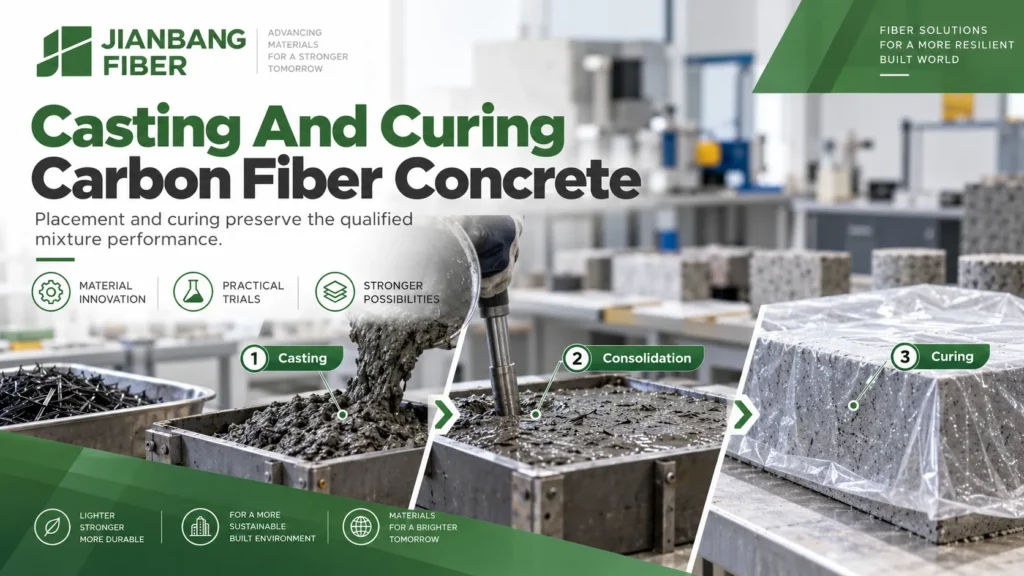
Chopped carbon fibers can reduce fresh flow or change how a mix consolidates. Confirm pumping, chute discharge, form filling, vibration, and finishability in a representative mockup. For a thin or congested section, verify that fibers pass around reinforcement and embeds without creating voids. For an exposed surface, inspect whether fiber ends affect the specified finish. Use the consolidation method that produced the accepted trial panel; excessive vibration can segregate a mixture and insufficient vibration can trap air.
Mold casting and shotcrete are different processes. A successful cast prism is not evidence that the same carbon-fiber mixture can be sprayed. Shotcrete requires separate equipment trials for nozzle behavior, rebound, build-up, bonding, and hardened-panel testing. Do not suggest a sprayed tunnel application solely because a cast mix dispersed well.
Protect fresh concrete from early drying and temperature extremes. Maintain the curing conditions and period required by the project specification, binder system, exposure, and test plan. A generic seven-day moist-curing rule or a 14-day rule for durability should not override the adopted standard or project conditions. Poor curing can mask a good fiber selection by weakening the matrix and increasing cracking.
Precast producers may use steam curing after a suitable delay, with controlled heating, hold, and cooling stages. A faster demolding cycle must be qualified with the actual binder and element. Check early strength, later-age performance, surface condition, and any temperature-induced cracking. Keep the production curing record with the fiber batch record.
Verify mechanical, durability, and functional claims
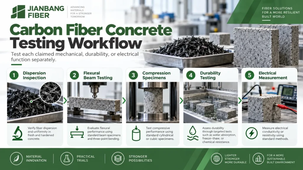
Test the property the customer is buying. For crack resistance under bending, ASTM C1609/C1609M-24 distinguishes first-peak strength from residual flexural strength after a crack and records toughness from the beam load-deflection response. Use the test method and acceptance values named in the contract. Specimen dimensions and fiber alignment affect the outcome, so compare like with like and confirm performance in a representative element when needed.
For a structural concrete grade, test compressive strength by the governing local method. A high tensile strength for an individual filament does not guarantee higher concrete compression. For a freeze-thaw exposure, check air-void requirements and use a specified procedure such as ASTM C666/C666M-26 where appropriate. Carbon fibers do not remove the need for a sound aggregate, suitable air entrainment, and curing. Water resistance, chloride ingress, and chemical exposure require their own relevant tests and detailing.
If electrical conductivity or strain sensing is the goal, specify electrode geometry, moisture and temperature conditioning, baseline resistance, load cycle, and response repeatability. Moisture and ionic conduction can affect a reading. Do not advertise “self-sensing concrete” on fiber content alone. Where conductive carbon materials might contact steel reinforcement in a wet, chloride-exposed environment, have the durability engineer assess the electrical and corrosion design for the specific system.
| Required claim | 요청할 증거 | Common false shortcut |
| Uniform dispersion | Discharge checks and cut or fractured specimen inspection | Assuming a smooth fresh surface proves uniform fibers |
| Crack bridging | Flexural response at specified deflections | Reporting only fiber tensile strength |
| Structural grade | Compressive specimens under the governing standard | Assuming fiber addition creates a strength class |
| Freeze-thaw durability | Air and exposure-specific performance tests | Treating the carbon fiber as a substitute for air entrainment |
| Conductivity or sensing | Electrical response under controlled conditioning and loading | Reporting one dry resistance value as a sensing system |
Common preparation mistakes and how to avoid them
Using a resin-composite fiber without checking its sizing. Ask how the surface was prepared and test wetting and bond in the target cement paste. The label “carbon fiber” does not establish cement compatibility.
Copying a dosage across different units. A percentage by cement mass can differ greatly from a percentage by total concrete volume. Put the unit and the conversion in the batch sheet.
Increasing fiber content before fixing dispersion. Higher content may increase the number of bundles. First confirm the feed rate, paste, dispersant, and mixer procedure.
Adding water to restore flow. Requalify the full mixture if the water-to-binder ratio changes. Use approved admixture adjustments and trial results to control workability.
Treating every performance claim as the same result. Crack control, residual flexural capacity, compression, freeze-thaw resistance, permeability, and electrical response need different acceptance evidence.
자주 묻는 질문
What carbon fiber length should I choose for concrete?
Begin with the section thickness, aggregate size, placement method, and target crack-bridging response. Shorter fibers may be easier to distribute, while longer fibers may change pullout and workability. Compare actual grades in a representative trial; a general 5–25 mm research window cannot replace that decision.
Is a 0.5% carbon fiber volume fraction always optimal?
No. It is one possible trial point. The best amount depends on the delivered fiber, base mixture, dispersion, fresh behavior, test results, and cost. State clearly whether a percentage refers to concrete volume, binder mass, or another basis.
Should I dry mix or disperse fibers in water first?
Both methods can be investigated. The selected sequence must separate fibers in the actual equipment and preserve the required fresh and hardened properties. If a dispersant or ultrasound works in a laboratory slurry, verify that its effect carries over to production.
Can carbon fibers replace conventional reinforcement?
Do not assume so. Discontinuous fibers and bars or continuous reinforcement have different load paths and design rules. Any substitution requires structural design approval, applicable code compliance, and measured composite performance.
Can this mixture be used for conductive or self-sensing concrete?
It may be a candidate. Qualify fiber distribution, contact network, electrode design, moisture sensitivity, repeatability, and the electrical response under the intended service conditions before making that claim.
Plan a carbon fiber concrete trial with Ecocretefiber™
Shandong Jianbang Chemical Fiber Co., Ltd. supplies fiber solutions under the Ecocretefiber™ brand, and our carbon fiber category is a starting point for a project inquiry. Tell us the element, base mixture, batch size, mixer, placement method, and target result. We can discuss a suitable fiber form and the information needed for a trial. Confirm the current grade data sheet, availability, and acceptance method before placing a project order. Contact the Ecocretefiber™ team to review your requirements.